|
The typical Chainless Conveyor system is a modular system in which few components can be utilized to form almost any configuration imaginable. By using idle corners, vertical curves and horizontal curves, a Chainless system can be customized to compliment operation.
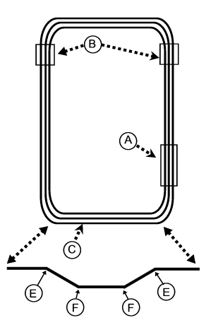
The sample below depicts a typical Chainless Conveyor System and describes all of its components
-
Connecting Rods: Chainless trolleys are connected by a series of rods.
-
4-Rail Track: The chainless straight rail is furnished in 20’ lengths and is fabricated from 1 1/2 X 1 1/2 angle
iron.
-
Trolley:
Chainless offers 8-wheel trolleys with exceptional stability for any conveyor application where trolley capacities do not exceed 400 pounds.
-
Track Adjusters (B): The LGB-896 Screw type Track Adjuster is supplied as a
complete set. The adjuster should be located on each side of a 180º if possible. After the initial adjustment when the installation is completed, there is seldom and further
take-up required
-
Curves: To assure proper clearance and alignment, all track curve assemblies are prefabricated at the factory.
-
Drive (A) : The AOC Chainless drive is supplied as a complete section of straight track. The endless system is pulled through the track by a series of trolleys connected together with rods.
-
Vertical Curves (C, D & E): The steel angle track assembly allows trolleys to travel smoothly around the formed horizontal or vertical curves without the use of turn sprockets or roller turns.
| TYPICAL
INSTALLATION METHODS |
OVERHEAD SUSPENSION
The LBG-877 hanger clip, which bolts to the top of the track plate, is fabricated for attachment of a threaded hanger rod at the clip center and a sway brace on each end if necessary. Sway brace may be welded or bolted. The other end of the
threaded hanger rod can be bolted to a ceiling cleat (LGB-901)
IN THE FLOOR
The inverted type chainless conveyor can be installed in the floor by lag bolting the track clips to the concrete base. Initial design of the conveyor system should
consider the required height of the trolley load attachments above or below the floor level to establish pit depth. After installation, flat steel plates should be added to cover the entire length of the conveyor, allowing only a clearance slot for the trolley load attachment.
FLOOR MOUNTED
When the Chainless Conveyor is installed in an inverted position, (Table-top pr pallet type) the trolley clevis is bolted to the top trolley wheel axles. Floor
mounted conveyor supports, in most cases, vary in height and are designed and fabricated to suit each
individual application. In cases where it is not desirable to support an overhead conveyor system from overhead building steel, floor mounted “A” frames or
stanchions can be used.
Chainless
Conveyor Menu
Anatomy
Calculation and Design
Sample Chainless Line Pull Calculation
Line Pull Determination
Track and Fittings
Trolleys
Trolley Attachments
Drive Assembly
How to Specify Curves
Corner Load Clearance Chart
How to Compute Vertical Curve Dimensions
Vertical Curves Load Clearance Chart
Load Table
|